A Simple Introduction to Radio
This article explains how simple circuits can be used to tune
into different radio signals.
Robert Lomas
Making Crystal Sets
As a short-trousered school boy I couldn't afford to buy a
radio, not on my restricted pocket money, so the only way to get one was to make
my own. It needed to be simple and it was. I made a crystal set.
Used toilet rolls, army-surplus wire, a condenser taken
from a broken radio set my grandmother had thrown away, were all pressed into
service. All I needed to buy from a radio junk shop was a cats-whisker, which
was the old name for a crystal diode, and a pair of ex-Army headphones.
I made wooden base to hold the bits in place. Next I wound
250 turns of enamelled copper wire round an empty toilet roll centre, borrowed
my school's only soldering iron to connect the condenser across it, and glued
the bits to the wooden base. My rather dashing headphones were connected through
the 'cats-whisker' across the toilet roll tuning coil. Now I needed an aerial
and an earth. I buried two square yards of chicken wire netting in the flower
bed under my bedroom window and connected it to bottom of the coil. This was my
earth connection. To the other end of the coil I connected 50 feet of 'Army
surplus' insulated copper wire, which ran from my bedroom window to the tree at
the bottom of the garden. Just one thing left to do. I connected a 'by-pass'
condenser, salvaged from the broken radio set, across the terminals of the
headphones. Now I had my own radio set. One coil, one variable capacitor, one
fixed capacitor, a rectifier, a pair of head-phones, an earth connection and a
length of wire slung out of the window to the nearest tree. And it worked first
time.
As I slowly turned the knob on the tuning condenser I
could hear the BBC Light Programme, then the Home Service and even the Third
Programme. How could a simple collection of bits and pieces of ex-War Department
junk be turned into a working radio receiver? It�s because the way of radio
works can be simple. If you make your aerial pretend to be the right length to
fit the radio waves of the station your want to hear, you will be able to listen
to it. But to me it was just a way to listen to Sub-Lieutenant Phillips as he
told Petty Officer Pertwee to put his 'left hand down a bit' to run HMS
Troutbridge into the dockside. These Sunday afternoon editions of 'The Navy
Lark' heard on a crystal set still make me smile.
I soon found there were other things to hear on the radio,
stations my simple crystal set couldn't tune into. If I twirled the dial of the
radiogram right down, as far as it would go, I heard people who had their own
private wireless stations. They were telling each other about the vast distances
their �short waves� had gone and bragging about the distant stations they
had �worked�. I wanted to know more - and curiosity drove my quest for a
cheap short-wave radio of my own.
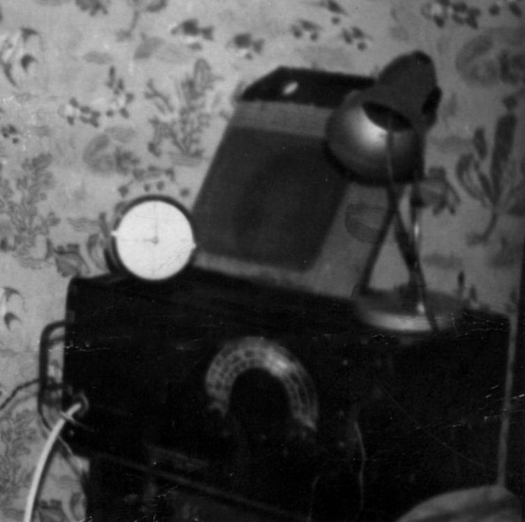
It took me months to save up enough money to buy myself a
bit of war surplus kit, a PCR2 communications receiver, which tuned the short
waves band from 1.8 to 30 Mhz. Now I was set up to really hear the world.
PCR2 stood for Pye Communications Receiver Model 2 and it
had been made by the Pye Electrical Company for army use in World War II. It was
a general purpose radio set which tuned the most useful short waves from 10
metres to 150 metres and many other short-wave broadcast bands. It had a socket
for me to plug in the headphones from my crystal set and what was even better, a
small built in speaker.and a jack-plug to fit and even bigger one, which of
course I did.
It was wonderful. Now I could tune the local broadcast
stations clearly, including the all important Radio Luxembourg. I could listen
to Horace Batchelor offering to make me rich by selling me a system to win the
football pools. His address, spelt K A N E S H A M, for those of you old enough
to remember his adverts were a regular interruption to the pop music. I am still
puzzled as to why he wanted to sell his secrets to me, why he didn't just use it
win a fortune for himself if it was so good?
My new radio set had a better tuning system and a more
accurate dial than the crystal set it replaced. It still worked in a similar
same way though, by fooling the radio waves into thinking that the aerial was
the right length to fit the signals I wanted to listen to. I was using the same
aerial I had put up for my crystal set but I could now �trim� it. My new set
had an aerial matching control and this enabled me to tune in very distant
stations. For the first time, if I listened at the right time of day I could
hear short wave stations in the United States, and from all over Europe.
To tune into the Light Programme, which was broadcast on a
wavelength of 1,500 I had fool the aerial into thinking it was 375 metres long.
This is why the aerial trimming knob was useful, it slowed down the radio waves
so they were felt as strong as if I had really put up a much longer aerial.
There are two ways to tune a radio receiver. You can
adjust the length of the aerial to exactly a quarter of the wavelength of the
transmitter signal. Or you can do some electronic fiddling with the aerial
signal so the set only hears the frequencies you want it to.
How Radio Tuning Works
I have been
casually using the term wave-length to talk about different radio stations so
here I explain just what I mean by the wave length of a radio wave.
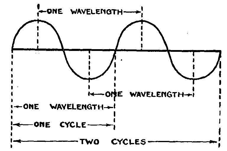
Here is a diagram of the carrier
wave of a radio station. As you can see it repeats, first creating a growing
positive voltage and then reversing to create negative voltage before starting
the whole cycle over again. Radio waves travel at a constant speed of
300,000,000 metres a second. So if the voltage went round the full voltage cycle
of starting from zero, positive swing, back to zero, negative swing and finally
back to zero in one second, the wave would have travelled 300,000,000 metres in
that time and that would be the length of the wave. You could have chosen any
point on the cycle to measure the wavelength as I've shown in the drawing.
That's rather a long wavelength but the faster the wave completes its cycle the
shorter the wavelength. For example if the wave completes a million cycles a
second (what we call 1 Mhz) then the wavelength will be 300,000,000 divided by
1,000,000 which is 300 metres. So the faster the wave oscillates the shorter the
wavelength of the signal. I mentioned when discussing dowsing that a water
molecule will vibrate at about 98 Ghz (98,000,000,000) which gives a wavelength
for its signal of about a quarter of a millimetre. So the faster the rate of vibration
the shorter the wavelength of the electromagnetic wave.
But let's stay with simple radio tuning circuits and
aerials.
Every aerial has a natural frequency it tunes, rather like
the string on a piano, the longer the string the deeper the note. In the same
way the longer the aerial the lower its frequency of reception will be. My
original aerial of 50 feet (about 24 metres) had a natural reception frequency
of 12.5 Mhz if it used its full length but radio waves don't work like that. So
what wavelength of signal would I hear if I listened to the natural reception
frequency from the end of my aerial? This diagram will help understand. It shows
the natural reception wavelength of an aerial.
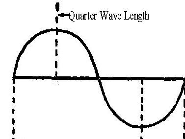
The signal which would give the strongest voltage response
to my aerial would be one four times longer than the wire, making it resonant at
a quarter of its wavelength. So listening directly to the output from the aerial
I would hear the strongest signal which would be any broadcast station with a
wavelength of 96 metres, or frequency of about 3 Mhz.
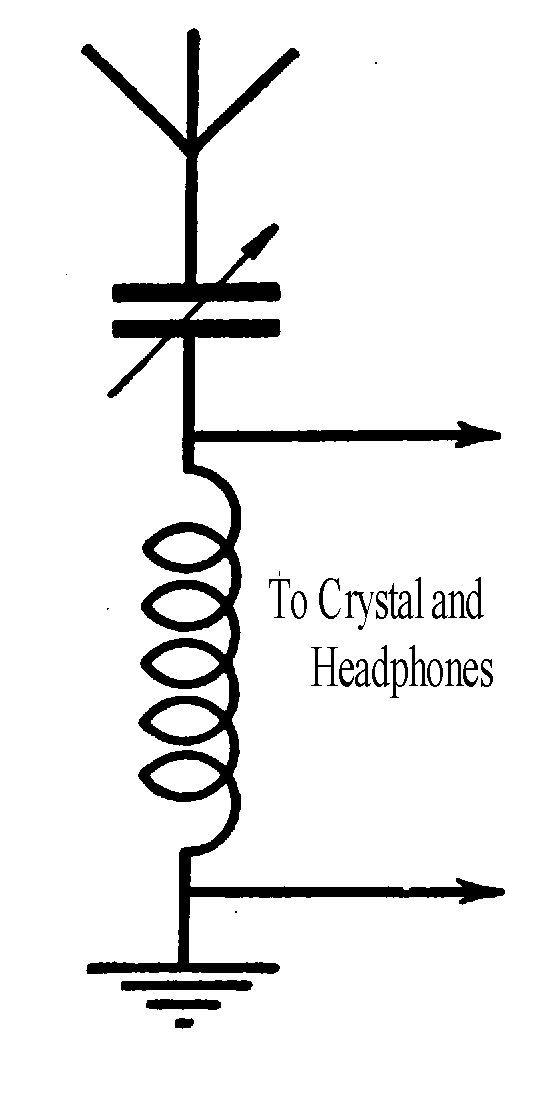
This circuit is called a rejector by engineers The
capacitor has to be there to compensate for the electrical interaction of the
coiled wire I had added to the end of aerial, as I will explain shortly. I
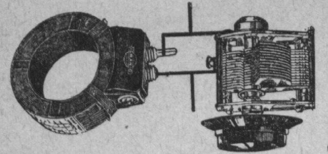
choose to use a rejector aerial tuning circuit to make make my crystal set. This
is what it looked like.
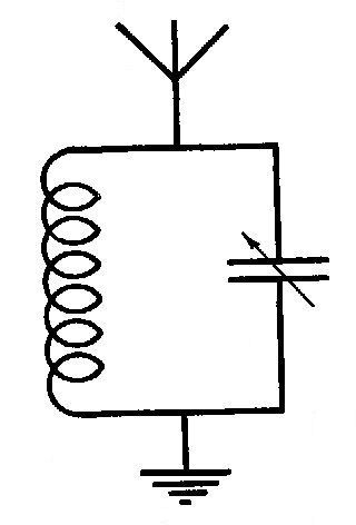
The variable capacitor had two sets of interleaved plates,
one set fixed the other movable and by turning the centre shaft the value of the
capacitance could be changed. Here is a drawing of what the circuit components
looked like as they lay on the bench.
The aerial will capture signals from many different
wavelengths, the strength of the signal being much higher near its natural
reception frequency and much less at other frequencies but this circuit can be
used to reject all the signals you don't want to hear and just allow the chosen
one to make it to the earphones. It does this using a property called resonance
which is a natural effect that amplifies small movements and makes them larger.
To understand resonance, imagine a child on a swing: the
first push starts the child moving to and fro; as the swing changes direction,
the child stops completely for a moment. If you continue to give the swing a
small push each time it pauses just before it starts a new cycle, then the speed
and movement will become faster and faster. Indeed, you will soon have to stop
pushing to avoid the child being pushed right over the top. This increase in the
amplitude of the swing by making small carefully timed pushes is called
resonance and it is how this coil and capacitor circuit works.
The cycle of events goes like this. When the current from
the radio wave hitting the aerial first beings to rise on the upper connection
of the coil-capacitor circuit, the capacitor is not charged. All the current is
sucked into the empty capacitor to charge it up. No current flows to the coil
because the uncharged capacitor looks like a short circuit and takes in all the
available electrons to charge it up.
Once the capacitor is charged up, the current can start to
flow to the coil. As it does, it makes a magnetic field around the turns of the
coil, as well as an electric field along the length of the coil. This combined
electro-magnetic field is a radio wave that travels off in all directions.
Imagine the waves like ripples that spread out on a pond when you throw in a
stone.
By the time the current in the coil has built up, the
alternating current from the aerial that was feeding the circuit will be
starting to die away, getting ready to reverse its direction for a new cycle. As
the supply current dies away in the coil, the stored charge in the capacitor
starts to flow. This discharges the capacitor into the coil and keeps the
electro-magnetic field in the coil going for much longer. Finally the capacitor
will discharge and the whole cycle will start again.
The speed at which this happens depends on the number of
turns, and the size of the coil, as well as the size of the capacitor. Different
pairs of coil and capacitor will respond at different frequencies. In this way
the circuit only magnifies the radio signal which matches the resonant frequency
of the circuit and it rejects all the others, hence engineers call it a rejecter
circuit.
This is not the only why to choose just one signal from
the cacophony of radio stations continually pulsing the aerial. I could have
arranged the same components like this drawing of an Acceptor Tuning Circuit for
a Crystal set.
If the natural resonance frequency of the coil and
capacitor match the transmitter frequency, the current from the capacitor worked
with the coil and magnified the current. If the natural frequency did not
coincide, the transmitter current would be over-ridden by the capacitor current
and they would cancel each other out.
|